Objective
This activity aims to develop the student’s ability to create a complete and accurate assembly drawing of the project. Emphasis will be placed on the application of standard technical drawing conventions, including proper dimensioning, tolerancing, sectional views, and annotation. The resulting drawing should serve as a reliable reference for manufacturing and inspection.
Materials and Equipment
The following materials and tools are essential for successfully completing this activity. Ensure they are available, complete, and in proper working condition before starting.
- Drawing Paper (8.5’’ $\times$ 13’’)
- Pencil (2B) and Eraser
- Technical Pens (0.5 and 0.2)
- Ruler and Scale
- Triangles
- Vernier Caliper
Procedure
Preparation
- Review the project design specifications, including all required dimensions and tolerances. Seek guidance from your instructor regarding the assigned values. A sample assembly drawing is provided on Figure 1.1.
- Prepare all necessary drawing tools and ensure your workspace is clean and organized.
Creating the Assembly Drawing
- Draw the border lines and title block, following the layout shown on Figure 1.2 and Figure 1.3.
- Sketch a rough layout of the assembly, identifying key components and their relationships. Select an appropriate scale for clarity and fit.
- Use proper projection methods (e.g., orthographic, isometric) to accurately depict the full assembly. Note that an isometric view is optional if all necessary details are clearly shown in the orthographic projection.
- Apply standard dimensioning and tolerancing practices, including hole sizes, keyway dimensions, and overall part limits. Avoid over-dimensioning.
- Add centerlines, labels, and annotations to highlight critical features.
Finalization and Submission
- Double-check all dimensions, tolerances, and notes for accuracy and completeness.
- Finalize the drawing using technical pens: 0.8-1.0 mm for border lines, 0.5 mm for visible lines, and 0.1-0.2 mm for hidden lines and centerlines.
- Remove construction lines to present a clean and professional drawing.
- Submit the completed assembly drawing to your instructor for review.
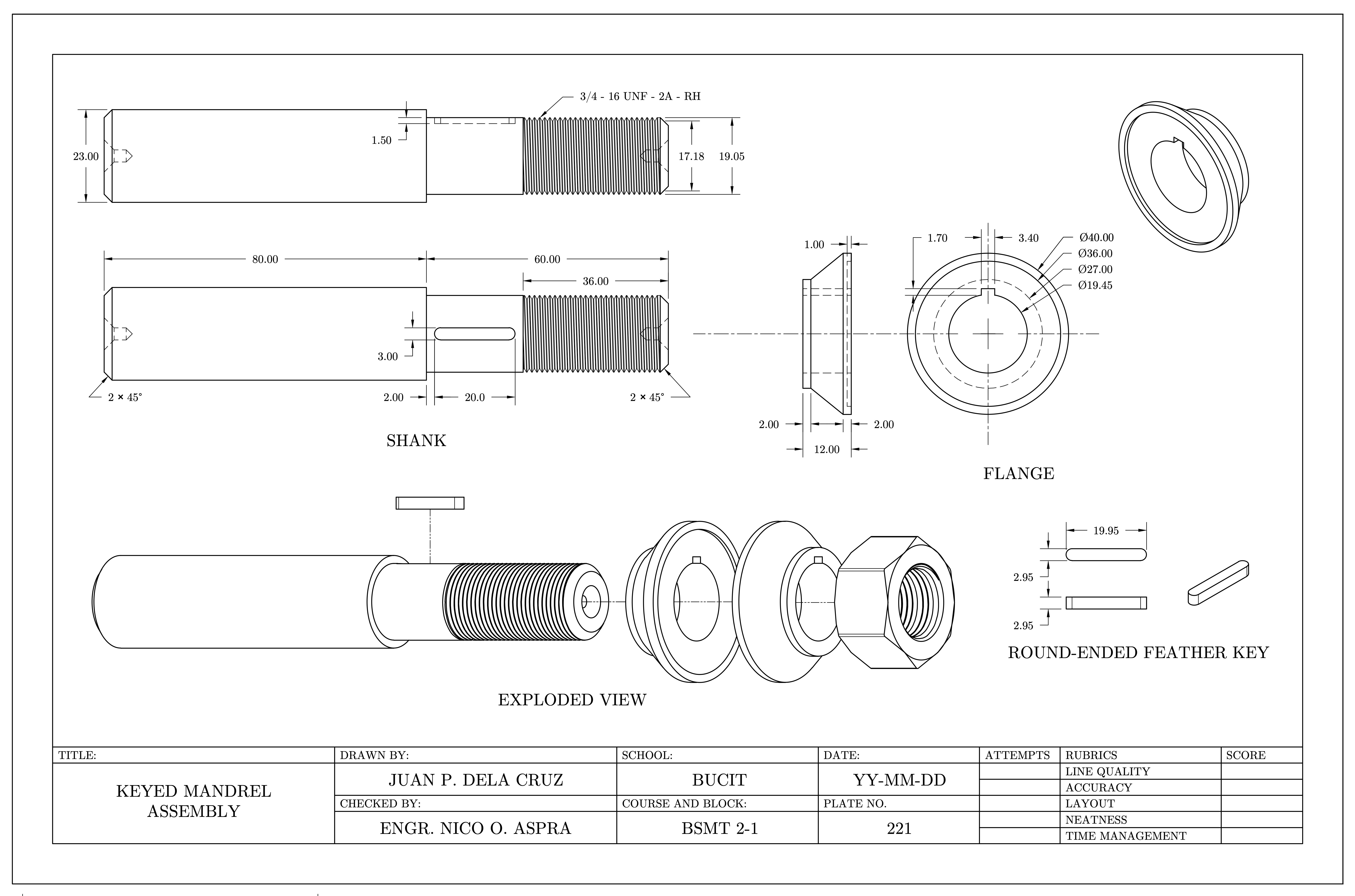
Figure 1.1: Sample assembly drawing of the keyed mandrel assembly. Students are required to draw only the necessary views for clarity; an exploded view is not required.
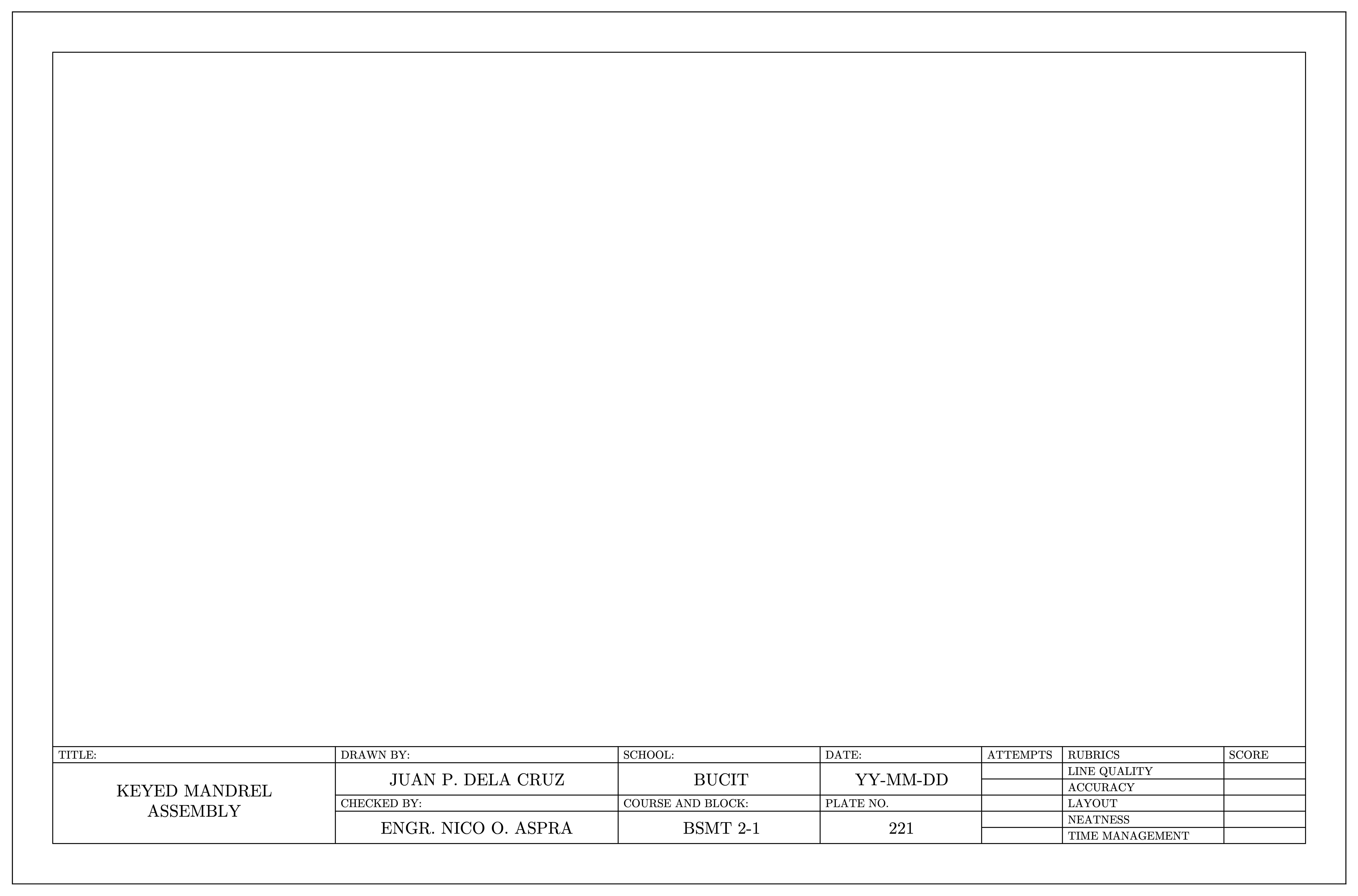
Figure 1.2: Title block layout template showing the required information, including project title, course, date, and student identification.
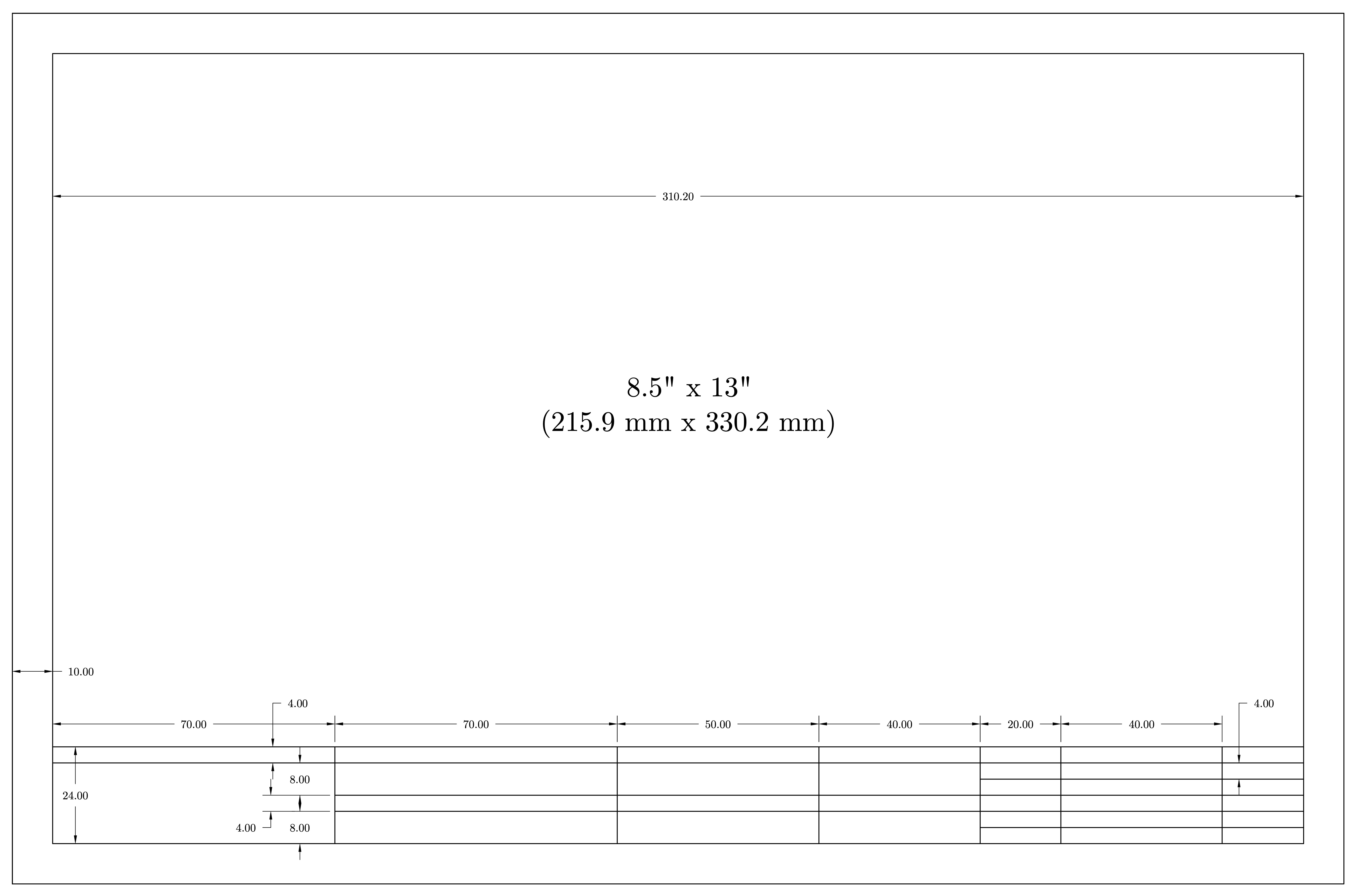
Figure 1.3: Dimensioned drawing border and title block layout. All dimensions are in millimeters and must be strictly followed.