Introduction
Before performing any machining operations, it is essential to understand how the lathe’s dials control tool movement and how backlash affects precision. This activity introduces students to the relationship between dial rotation and the actual linear displacement of the tool. It also highlights the role of backlash and how it can impact machining accuracy.
Objective
This activity aims to measure and analyze the dial graduations, backlash, and corresponding linear movement of the various dials on a lathe machine. By recording and comparing data from two different machines, students will gain insight into how factors such as machine wear, calibration, and model differences influence tool control and dimensional accuracy.
Materials and Equipment
The following materials and tools are essential for successfully completing this activity. Ensure they are available, complete, and in proper working condition before starting.
- Lathe Machines (two different units for comparison)
- Vernier Caliper
- Dial Indicator (optional, for verifying backlash more precisely)
Procedure
Selecting a Lathe Machine
- Choose two available lathe machines in the shop.
- Start by focusing on one machine before proceeding to the second.
- Locate the three primary dials:
- Compound rest dial
- Cross slide dial
- Carriage handwheel dial
- Ensure the machine is clean and that all dials are easily readable.
- Identify the portion of each dial with metric graduations.
- Determine the total number of graduations per full revolution for each dial and record the values in Table 2.1 (in the Laboratory Worksheet).
Understanding and Compensating for Backlash
- Move each dial forward by 2-3 revolutions, then reverse it slightly.
- Observe whether the tool immediately moves backward or if there is a delay.
- Measure how much movement is lost before the tool reverses direction.
- Using the recorded dial graduations, determine and record the backlash values for the compound rest, cross slide, and carriage handwheel in Table 2.1 (in the Laboratory Worksheet).
- Learn proper techniques to compensate for backlash when setting tool positions.
Exploring Dial Movements
- Zero all lathe dials and set up a fixed reference point to measure the linear displacement accurately using a vernier caliper.
- Begin with the compound rest dial:
- Rotate the dial one full revolution and measure the displacement using the vernier caliper.
- Repeat for 2 and 5 revolutions, recording the total displacement.
- Compare the measured movement with the dial readings.
- Repeat the same steps for the cross slide and carriage handwheel.
- Record all readings in Table 2.1 (in the Laboratory Worksheet).
- Move to the second lathe machine, repeat the entire process, and record all data in Table 2.2 (in the Laboratory Worksheet).
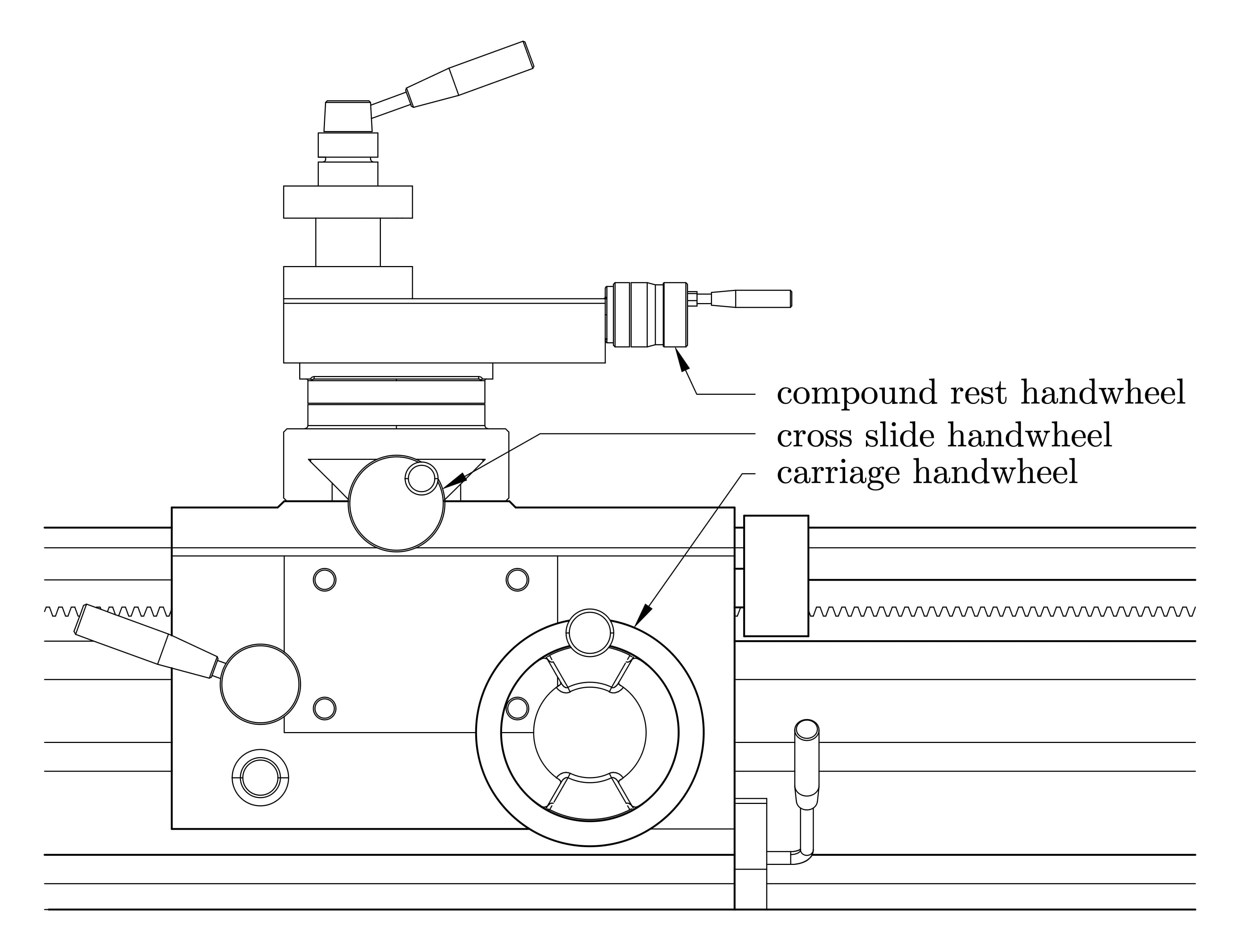
Figure 2.1: Locations of the compound rest, cross slide, and carriage handwheels. The dials are integrated into these handwheels and are usually found directly behind or surrounding the rotating portion, serving as the reference for tool position and movement measurement.