Objective
This activity aims to perform facing and center drilling operations on a cylindrical workpiece using a lathe machine. Students will develop skills in machine setup, tool alignment, automatic feed operation, cutting speed selection, and proper safety practices to achieve precise surface squareness and accurate center holes.
Materials and Equipment
The following materials and tools are essential for successfully completing this activity. Ensure they are available, complete, and in proper working condition before starting.
- Assembly Drawing
- Workpiece (AISI 1020, CRS $\varnothing$25.4 mm $\times$ 150 mm)
- HSS or Carbide Facing Tool
- 220 Grit Sandpaper
- #3 Center Drill
- Vernier Caliper
- Safety Goggles
- Lathe Machine with a 3-Jaw Chuck
- Chuck Key
- Tool Post Key / Allen Wrench (depending on the machine)
- Drill Chuck
- Drill Chuck Key
Procedure
Preparation and Setup
- Insert the workpiece into the 3-jaw chuck, leaving at least 1 inch of material exposed for machining. Ensure that the workpiece is tightly clamped and aligned to avoid wobbling during rotation.
- Set the compound rest to 0 degrees to ensure precise tool movement during the facing operation.
- Mount the facing tool on the tool post. Ensure that the tool is set exactly at the vertical center of the workpiece (see Figure 3.1a), with the cutting point slightly angled toward the workpiece for optimal cutting (see Figure 3.1b).
- Set the lathe spindle to the appropriate speed for the material and the roughing feed rate using the feed rate chart. For rough cuts, a lower speed is recommended.
- Double-check that all components (chuck, tool post, etc.) are securely tightened. Before turning on the lathe, manually rotate the chuck at least one full revolution to ensure there is no misalignment or interference. If any issues are detected, recheck your setup and make necessary adjustments.
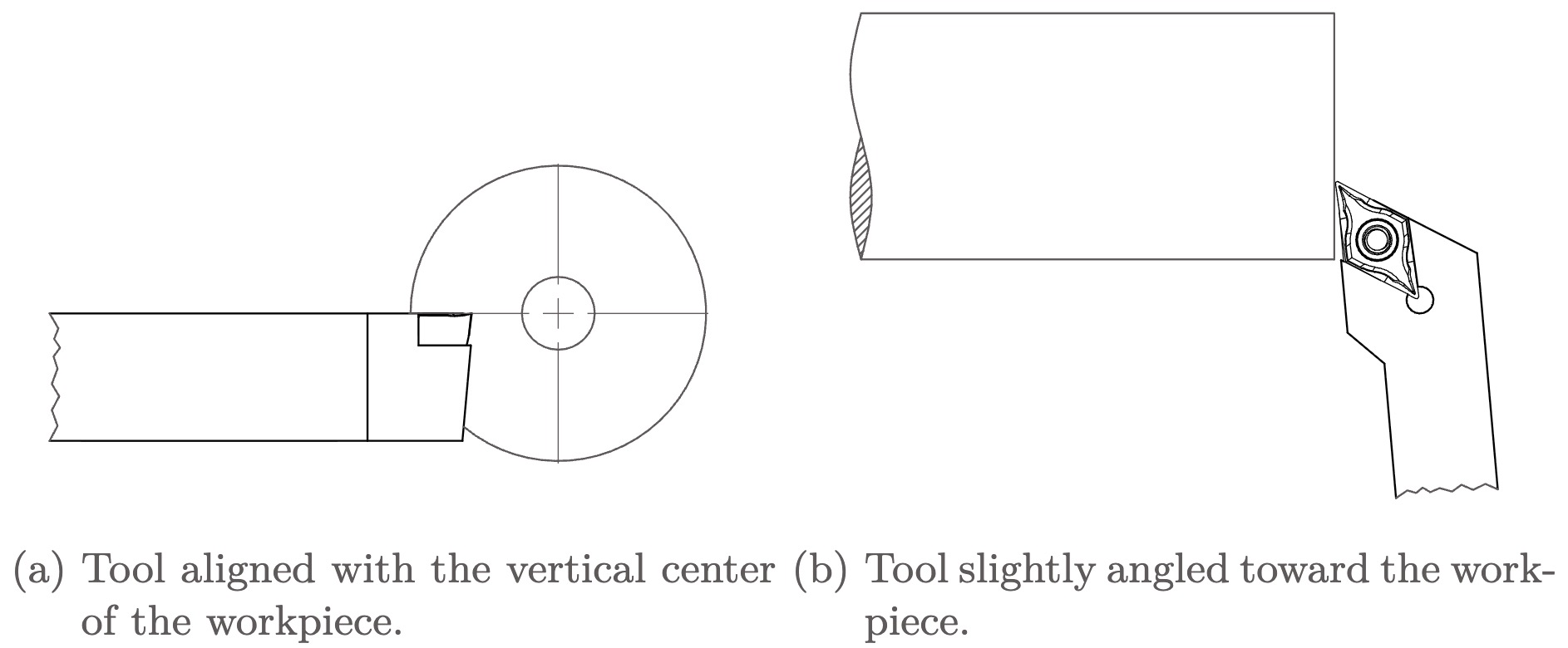
Figure 3.1
Manual Facing
- Turn on the lathe and manually face the workpiece. Use the compound rest to gradually advance the tool bit for each cut, ensuring a uniform layer is removed until the entire face of the workpiece is flat.
Automatic Feed Setup
- Set the automatic feed rate according to the feed rate chart. Experiment with different configurations to determine which produces the best surface finish.
- Engage the automatic feed by pulling the lever that switches the feed rod and lead screw. Verify that the feed rod is rotating instead of the lead screw.
- Use the power feed select lever to switch from longitudinal carriage feed to cross slide feed.
- Test the power feed by turning on the lathe with the feed clutch initially disengaged and away from the workpiece. Ensure it operates correctly and moves in the correct direction before making a cut.
- Once the feed is operating correctly, proceed with finer cuts using the automatic feed. Make small adjustments with the compound rest and adjust the spindle speed and feed rate to achieve a smooth surface finish.
- Record the spindle speed, depth of cut (compound rest increment), and feed rate used during the facing process in SI units (see Table 3.1 in the Laboratory Worksheet). Analyze how these parameters affect the surface finish quality.
Center Drilling
- Adjust the tool bit angle slightly inward while ensuring it remains vertically centered. Use the tool bit to create a small pilot hole precisely at the center of the faced surface.
- Insert the drill chuck into the tailstock and secure the center drill bit. Drill to the specified depth, ensuring that the drill aligns perfectly with the pilot hole to prevent off-center drilling.
Machining the Opposite End
- Remove the workpiece from the chuck and use a Vernier caliper to lock the desired length of the workpiece. Using the faced side as a reference, mark the length for machining.
- Rotate the workpiece, secure it in the chuck again, and repeat the facing and center drilling processes on the opposite side of the workpiece.
Final Measurements
- Use a Vernier caliper to measure and verify the final dimensions of the workpiece.
- Record the final dimensions and compare them with the project specifications (see Table 3.2 in the Laboratory Worksheet).