Objective
This activity introduces students to the process of cutting external threads on a previously turned workpiece. Students will first create a thread relief and then set the compound rest to $29\degg$ to perform threading using the compound rest feed. The activity emphasizes proper alignment, precise tool setup, safe operation, and accuracy in producing threads that meet specification.
Materials and Equipment
The following materials and tools are essential for successfully completing this activity. Ensure they are available, complete, and in proper working condition before starting.
- Workpiece from previous activity
- HSS Threading Tool (Ground to $60\degg$)
- Vernier Caliper
- Thread Pitch Gauge
- $60\degg$ Center Gauge
- Lathe Machine with Threading Dial Indicator
- Safety Goggles
- Chuck Key
Procedure
Preparing the Thread Relief
- Compute the theoretical thread depth and minor diameter based on your design. Show your solution in the ``Calculations'' section.
- Mount the workpiece using the same center-to-center setup with the lathe dog and centers.
- Using the crossfeed dial, turn a thread relief groove at the end of the threaded portion (see Figure 5.1).
- Ensure that the relief matches the calculated thread depth and results in a minor diameter equal to that of the final thread.
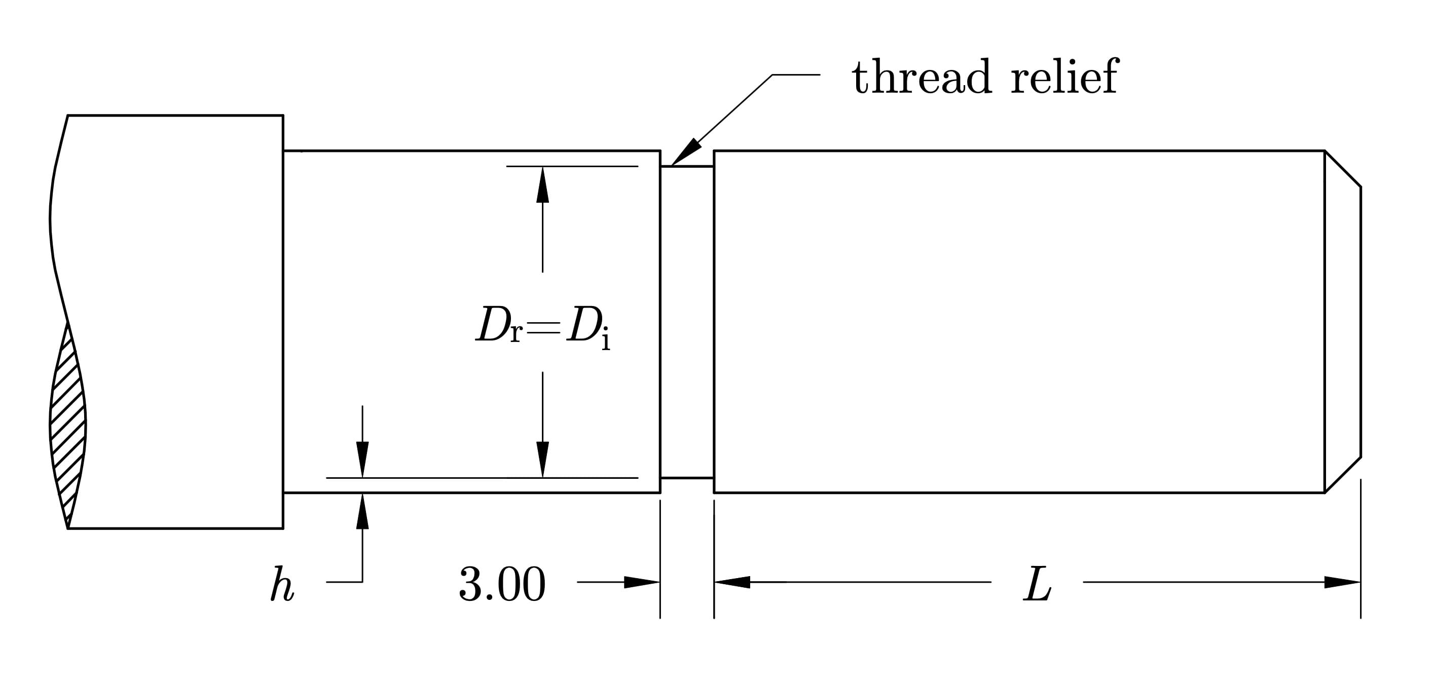
Figure 5.1: Cutting a thread relief at the end of the threaded section to allow for clean tool retraction.
Setting Up the Compound Rest
- Rotate the compound rest to $29\degg$ relative to the axis of the workpiece (see Figure 5.2a). Feeding the tool at an angle causes it to cut primarily on one flank of the thread, reducing tool load and resulting in a smoother, more accurate thread profile (see Figure 5.2b).
- Lock the compound rest securely.
- Mount the threading tool in the tool post and adjust its height so the tip is aligned with the center of the workpiece.
- Use the center gauge to verify that the tool is perpendicular to the workpiece axis (see Figure 5.3).
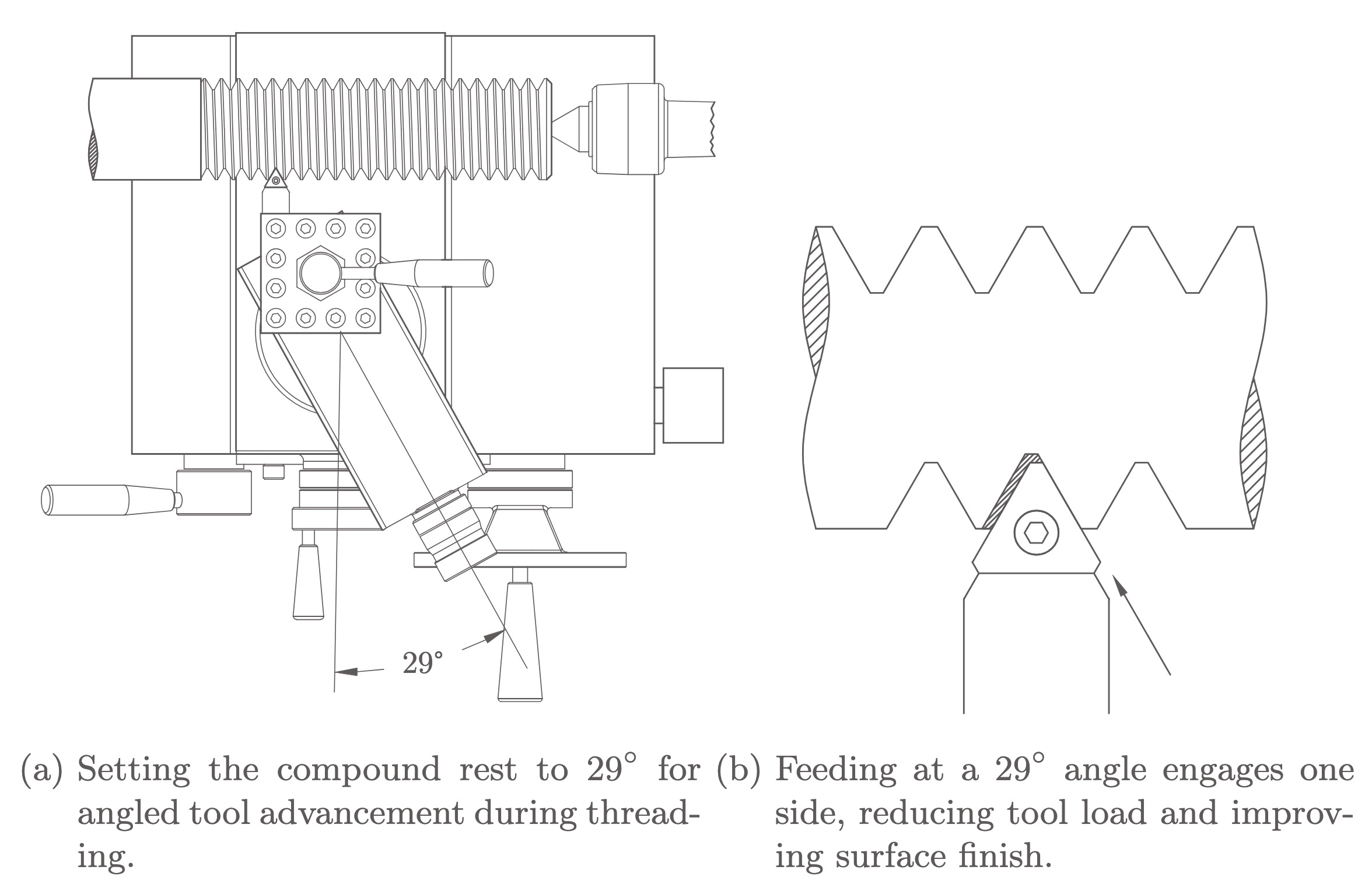
Figure 5.2:
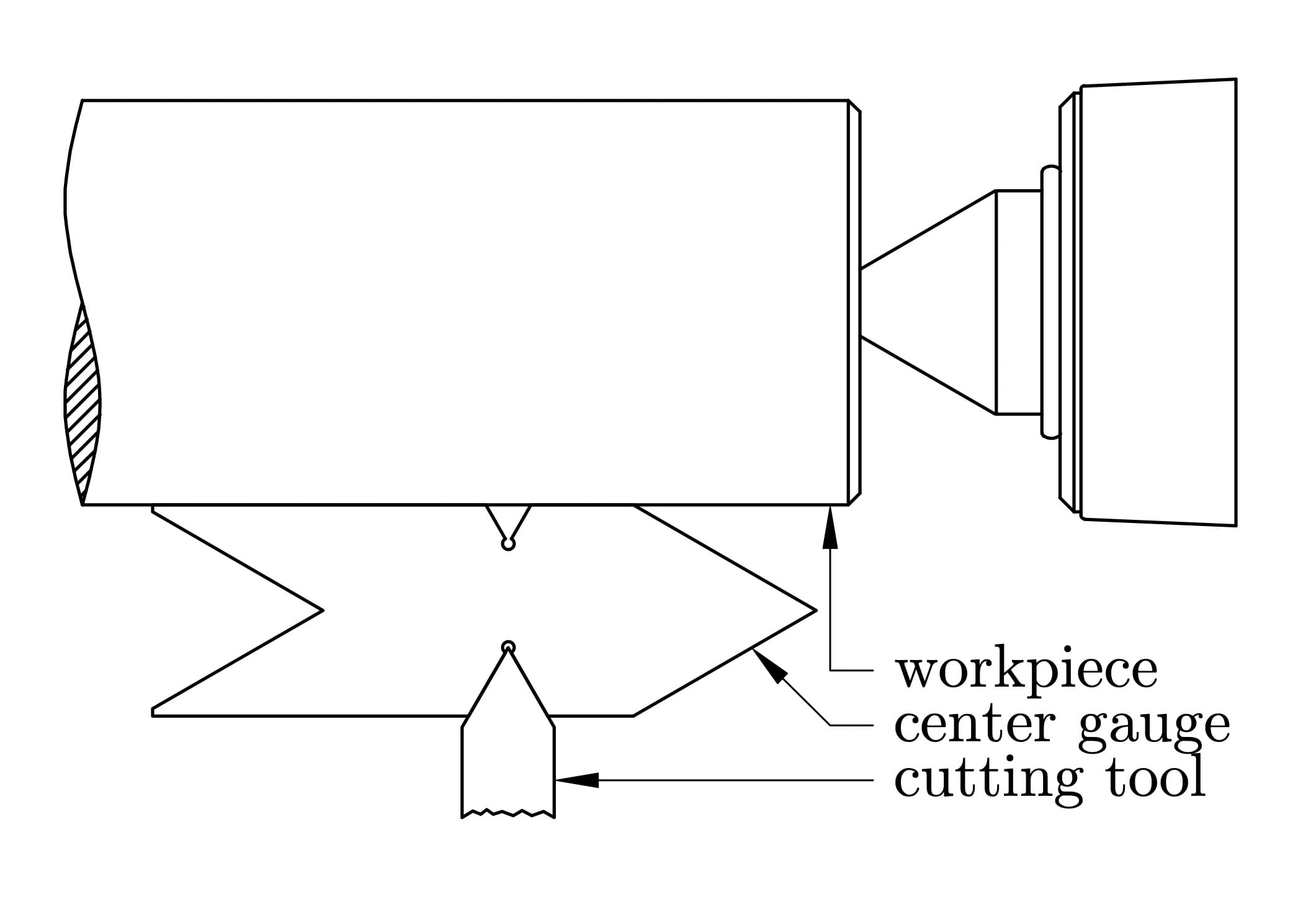
Figure 5.3: Aligning the threading tool using a $60\degg$ center gauge to ensure it is perpendicular to the workpiece.
Thread Cutting Operation
- Verify that the threading dial indicator is functioning properly and is easy to read.
- Set the spindle speed to a low RPM suitable for threading, typically between 60--100 RPM.
- Feed the threading tool into the workpiece using only the compound rest.
- Engage the half-nut lever when the threading dial aligns with the correct number for your thread pitch.
- After each pass, disengage the half-nut, retract the tool using the crossfeed, and return the carriage to the starting point.
- Make an initial pass and check the thread using a thread pitch gauge to confirm that the pitch is correct (see Figure 5.4).
- Advance the compound rest slightly and repeat the cutting process until the desired thread depth is reached.
- Deburr and clean the threads using a fine file or emery cloth to remove sharp edges and improve finish.
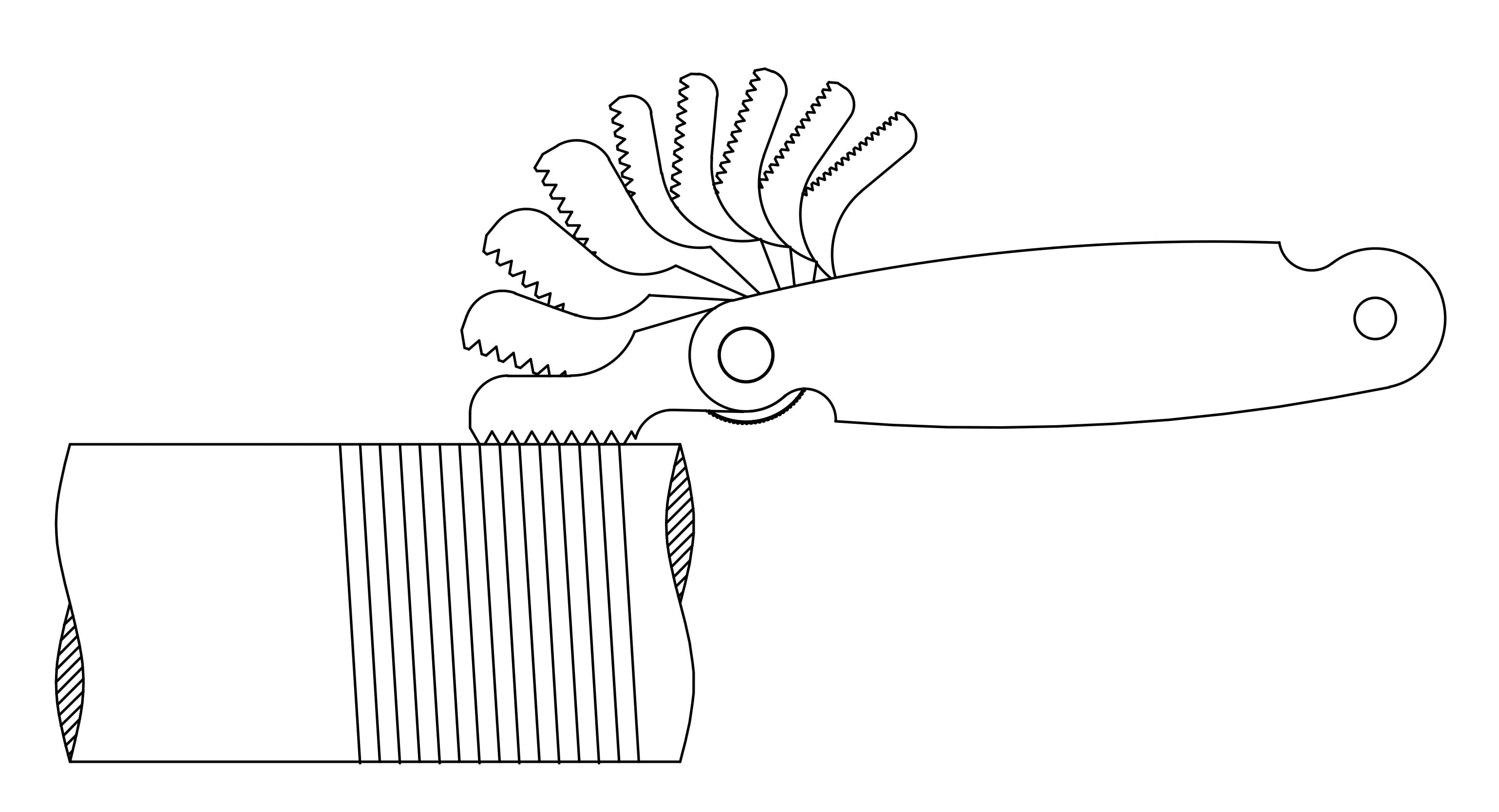
Figure 5.4: Verifying the thread pitch after the initial pass using a thread pitch gauge.
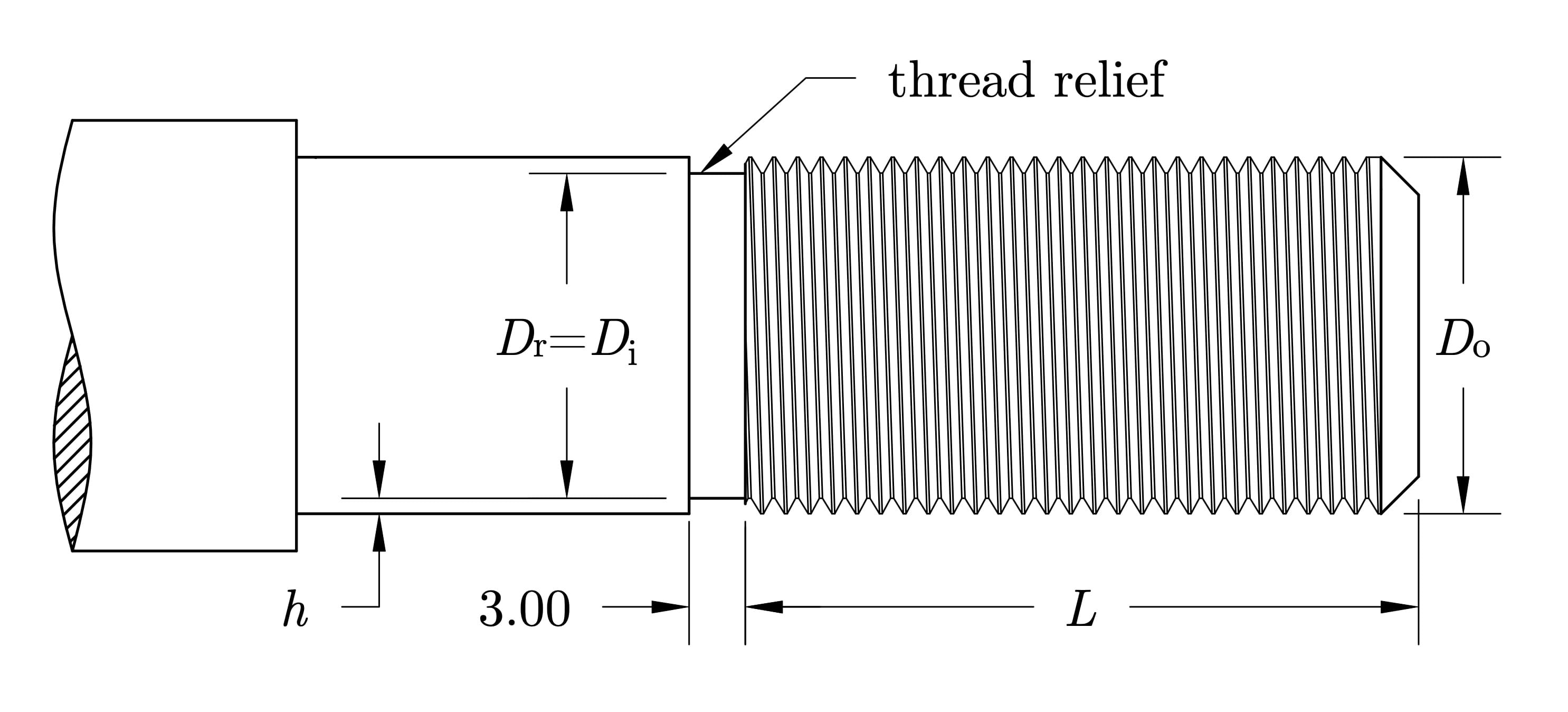
Figure 5.5: Completed external thread after final pass and cleanup.
Testing the Thread Fit
- Check the thread fit using either the 3-wire method or a matching nut.
- If the fit is tight or uneven, take light passes to clean or slightly deepen the thread.
- Record your final thread dimensions and compare them to your calculated values and design specifications.