Objective
This activity introduces students to the precision operations of drilling, boring, and facing on a flange. Through this task, students will learn to accurately locate the hole center, safely perform through-drilling, enlarge the hole via boring, and achieve a smooth surface finish by facing the flange face.
Materials and Equipment
The following materials and tools are essential for successfully completing this activity. Ensure they are available, complete, and in proper working condition before starting.
- Workpiece (AISI 1020, CRS $\varnothing$50.8 mm $\times$ 30 mm)
- HSS or Carbide Facing Tool
- Center Drill
- Twist Drills (varying sizes)
- Boring Bar
- Parting Tool
- Vernier Caliper
- Lathe Machine
- Chuck Key
- Safety Goggles
- Drill Chuck
- Drill Chuck Key
Procedure
Locating and Drilling the Center Hole
- Rough cut the bar stock to a length equal to twice the flange thickness, plus an additional machining allowance (approximately 5--10 mm), since the workpiece will be parted into two separate flanges.
- Mount the workpiece securely in the chuck. Ensure it is clamped firmly to prevent slippage during the drilling operation.
- Use a center drill to spot the hole at the center of the flange face. This initial hole ensures accurate alignment of the twist drill.
- Drill a pilot hole using a small-diameter twist drill to establish the initial depth and alignment.
- Gradually enlarge the hole using incrementally larger twist drills until reaching the largest available twist drill that closely approaches the desired final diameter. Drill through the full length required for both flanges.
- Perform a test fit using the threaded section of the shaft (the first workpiece). If the hole does not yet fit the shaft, proceed to the boring step; otherwise, you may skip it.
Boring to Final Diameter
- Mount the boring bar securely on the tool post and align it with the center of the drilled hole.
- Gradually enlarge the hole using light boring passes.
- After each pass, measure the hole diameter using a vernier caliper.
- Stop boring once the internal diameter matches the design specification.
Facing the First Surface
- Position the facing tool square to the face of the workpiece.
- Set the crossfeed zero reference and feed the tool evenly across the face to produce a smooth, flat surface.
- Continue facing until the desired surface finish is achieved.
- Reposition the tool bit or switch to a grooving tool if necessary.
- Machine the specified face relief based on the specification, leaving a narrow outer rim as the contact surface.
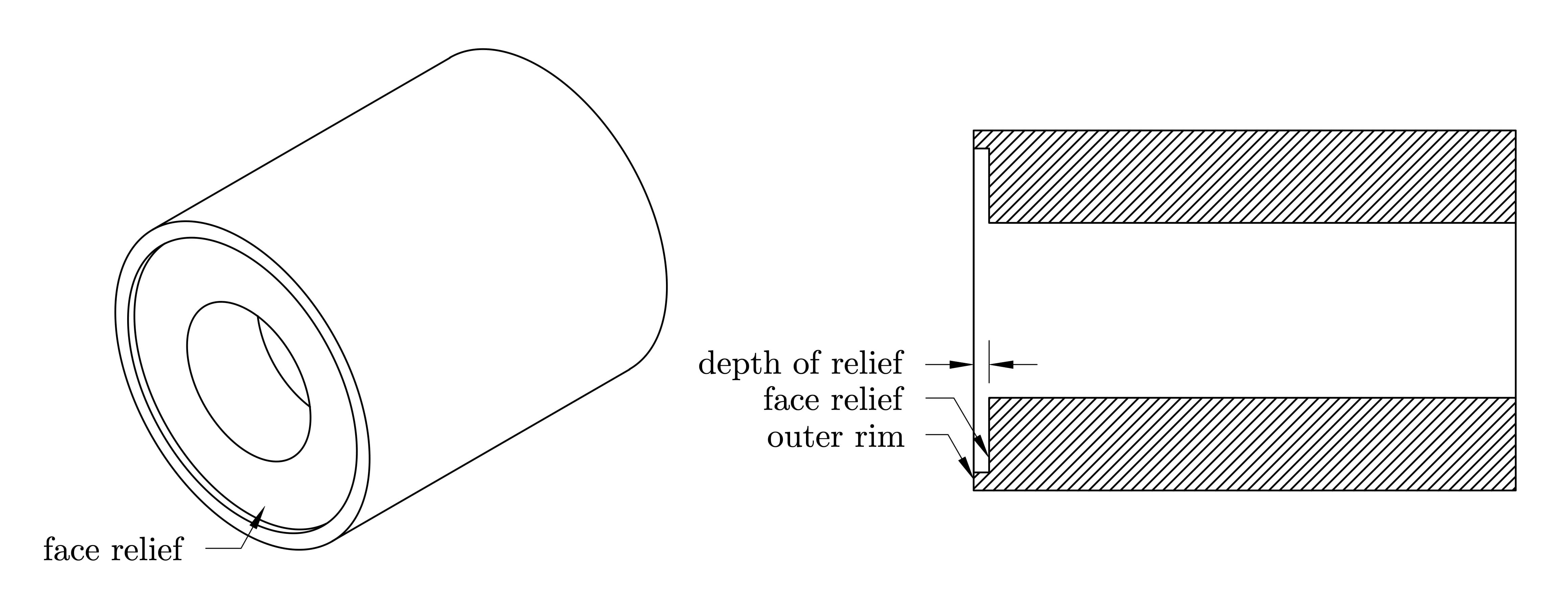
Figure 7.1: Face relief machined into the flange with a narrow outer rim.
Parting the Flange
- Mount the parting tool square to the workpiece and ensure it is set at the correct center height.
- Position the tool to match the desired flange thickness. Add a small allowance (approximately 0.5-1.0 mm) for final facing after parting.
- Set the spindle speed to a low RPM suitable for parting operations.
- Apply cutting fluid if available, and slowly feed the parting tool into the workpiece.
- Continue feeding until the first flange is fully parted from the bar stock.
- After parting, lightly face the new end of the bar to prepare for machining the second flange.
Facing the Opposite Side
- Remount the parted flange with the unfinished side facing outward.
- Use the twist drill (still mounted in the tailstock) as a visual guide to approximately center the flange.
- Face the surface evenly until the final specified thickness is achieved.
- Repeat the same process for the second flange.
- Measure the final thickness and visually inspect the surface quality.
Final Measurements
- Use a vernier caliper to measure and verify the final dimensions of each machined flange.
- Record your measurements and compare them with the design specifications in Table 7.1 (in the Laboratory Worksheet).